|
MODULE 6-9 GRATINGS Ó Copyright 1988 by The Center for Occupational Research and Development All rights reserved. No part of this book may be reproduced in any form or by any means without permission in writing from the publisher. The Center for Occupational Research and Development Printed in the U.S.A. ISBN 1-55502-024-0 (1) A diffraction grating is a glass or polished metal surface on which a large number of very fine, parallel grooves or slits are cut. These parallel elements are used to diffract light, generally both separating and spreading different wavelengths or colors. Diffraction gratings are manufactured on flat or curved surfaces according to their use. (2) Diffraction gratings are used in spectrographic equipment (spectroscopes, spectrophotometers, monochromators, spectrographs, spectrometers, and so on) as the principal optical element to separate light into its component wavelengths (frequencies) by diffracting them at various angles. Gratings also are used in some lasers that are capable of emitting a coherent output at more than one wavelength. In this application the grating is used to select a desired narrow wavelength range for the laser output. (3) This module will acquaint you with the types of diffraction gratings available, how they work, and how and when to use them in optical experiments. (4) Before you study this module, you should have studied elements and operation of a laser, coherence, propagation, interference, and diffraction. You also will find a knowledge of light helpful. Algebra and trigonometry are required to successfully complete this module. (5) When you complete this module, you should be able to do the following:
DISCUSSION (6) A highly periodic arrangement of finely spaced, parallel apertures is called a diffraction grating. The very first grating was used by a German physicist and astronomer, Joseph Von Fraunhofer. It consisted of a grid formed by winding fine wires on two parallel screw threads. This early diffraction grating looked similar to the one shown in Figure 1. The system had many obvious disadvantages.
Fig.
1 (7) Present-day gratings consist of equidistant line rulings on a flat glass plate (transmission grating) or on a flat mirror (reflection grating). Depending on the application, the number of lines per millimeter typically ranges from less than one hundred to several thousand. Because of this extremely fine spacing, the lines are carefully scribed with a diamond tool in a special machine called a "ruling engine." (8) Ruling a master grating is a very slow and highly controlled process. As you can imagine, producing a master grating is quite time consuming and costly. So the masters produced are used for making copies called "replicas." The replicas are made less expensively than the original by using a plastic or glass casting of the master grating. (9) Today holographically recorded diffraction gratings are gaining wide acceptance. Holographically ruled diffraction gratings eliminate some of the problems encountered when the groove spacing is not perfect. They can be obtained with rulings as fine as 6000 lines per millimeter, which gives them high resolution. However, the efficiency of such gratings is typically lower than that of conventionally ruled gratings. (10) You need an appreciation of diffraction theory to understand the operation of a diffraction grating. We won’t go into a thorough discussion of diffraction theory here, but a short review is appropriate at this time. (11) The bending of a wave front as the wave passes through an opening or around an obstruction is a common example of diffraction. As an opening becomes much larger than the wavelength, diffraction effects become less noticeable. All periodic waves exhibit diffraction effects, but under certain conditions, such as broad spectral bandwidth, it may be hard to see the effects. Figure 2 shows diffraction taking place when plane waves pass through an aperture—such as a long narrow slit perpendicular to the page.
Fig.
2 (12) When two such openings exist near each other, interference with other transmitted waves will result. This effect is shown in Figure 3 where monochromatic light waves are incident on two long, narrow, adjacent slits. The diffracted light through the slits may travel different distances before meeting at the screen. So the crests of one set of light waves may not necessarily coincide with the crests of the other. 
Fig. 3 (13) Where crest and crest coincide on the screen, a region of brightness appears, and where a crest and trough coincide a region of darkness appears. The successive regions of brightness and darkness are called "interference fringes." (14) A graph of the intensity of the light on the screen after interference is shown in Figure 4. Notice the uniformity of the pattern.  Fig.
4 (15) Figure 5 shows that light from S1 and S2 travels different distances to a given point P. The two rays arriving at P were in phase when they left slits S1 and S2 since both originated from the same wavefront in the incident plane wave.
Fig.
5 (16)
Because the rays travel different optical path lengths in reaching P,
they arrive at P with a phase difference. The number of wavelengths
in the path length difference (17) When there are three narrow, equally spaced slits, the interference pattern, instead of becoming more complicated, actually becomes more distinct. The additional slit imposes an extra condition on the three beams of light if they are all to interfere constructively at the same place. This has the effect of narrowing the bright region and at the same time making it brighter, since more light is concentrated there. Figure 6a shows a three-slit interference intensity pattern. Note the "secondary maxima" that appear between the "principal maxima." The number of secondary maxima increases as the number of slits increases, although, as shown in Figure 6b, the brightness of each secondary maximum decreases, until, with many slits, they disappear altogether, leaving only the principal maxima. When there are a large number of slits (thousands of them per centimeter) a diffraction grating is formed.
Fig.
6 (18) A clearer picture of the increased narrowing of the principal maxima with an increase in the number of slits is shown in Figure 7, for an increase from 5 slits to to 10 slits. For each case, seven orders of diffraction are shown, i.e., from m = 1 to m = 7. (The order of diffraction m is explained with Equation 1). As the order increases, the principal maxima are diffracted further and further from the spot locating the normal to the grating and is accounted for by the term "sin qm," defined in Equation 1. Note that as the diffraction order increases, the intensity or brightness of each principal maximum decreases.
Fig.
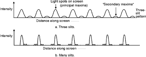
7 (19) Figure 8 shows a diagram of a transmission and reflection grating. The diffraction orders, to either side of the incident beam (m = –1, 0, +1, etc.) are also shown. The difference between the two gratings is that the transparent slits are considered to be individual "point sources" of light in the transmission grating while small reflecting surfaces are considered to be the individual "point sources" in a reflection grating. (20) Transmission gratings seldom are used today. One reason for this is that light must pass through the glass or other material that forms the grating. So the light is subject to absorption and distortion caused by that material. Another reason is that reflection gratings yield more compact systems, because of the "folding" of the optical path through reflection. 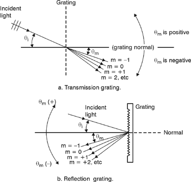
Fig.
8 (21) The position of a bright fringe on the screen is a function of the wavelength of light incident on the grating. As a result, different wavelengths—each a principal maximum—are focused at different locations on the screen. If the grating is illuminated by "white" light, the light is separated by the grating into its component wavelengths much as it is separated by a prism. (22) The utility of a grating depends on the fact that there are unique sets of directions. For a given groove spacing and a given wavelength of light along these directions, the diffracted light from all the grooves is in phase. (23) The grating equation that governs the location of the principal maxima as a result of diffraction is:
(24) Gratings are generally identified in terms of lines per inch or lines per millimeter. From this information, one can easily calculate the grating spacing a. For example, think of the lines that mark the "eighth" divisions on an inch ruler. There are 8 of them, starting just beyond the edge of a given inch mark. The spacing between the "eighth" lines are, as you know, one-eighth of an inch. You get this by dividing the inch length by 8 lines, getting 1/8 inch/line, or just 0.125 inch. It's the same way with a grating. If the grating has 8,000 lines per inch, then the grating-spacing is:
(25) If the grating has 2000 lines per millimeter, then the grating spacing is
(26) You can visualize the meaning of the symbols in Equation 1 better from the geometry of Figure 9. Here a plane wavefront is incident on a grating surface at an angle qi measured with respect to the grating normal. Then, via reflection, it’s diffracted at an angle qm measured with respect to the same normal. The groove spacing is designated by a. Notice that qi and qm are not necessarily equal due to the fact that light diffracts in all directions from the thin strips of polished surface between the grooved lines. Fig.
9 (27)
You can see by Equation 1 that, for a
given order m and grating spacing
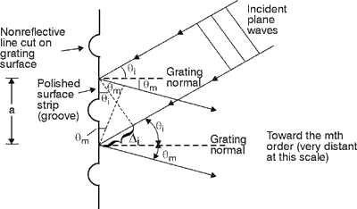
a, there is a mathematical relationship
between the wavelength of
the incident light and the angles of the incident and diffracted
rays. See in Figure 9 that the geometrical
path difference between light diffracted from successive grooves is
simply (28) So when light of wavelength l hits a grating at a given incident angle, there’s a unique set of diffraction angles at which the light will leave the grating, reinforced one for each different order. At all other angles its intensity will be reduced. This property lets us use gratings in instruments to measure wavelengths of light and to study the structure and intensity of spectral lines. Such instruments include spectroscopes, spectrophotometers, monochromators, spectrographs and spectrometers. (29)
Further interpretation of Equation 1 shows that, for certain
sets of angles qi and qm and groove spacing
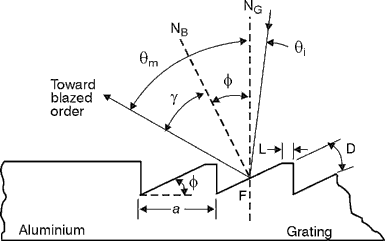
a, the grating diffracts
the light into different orders (30) The most troublesome aspect of the multiple-order behavior of gratings is that successive orders can overlap. For example, the violet wavelength 400 nm of the second order (m = 2) will reinforce at the same position on the screen as the deep red wavelength 800 nm of the first order. (31) We can overcome the overlapping of multiple orders by suitable filtering or by detector selectivity. More overlapping of wavelength regions occurs in the higher spectral orders than in the lower orders.
Efficiency (32) Two forms of efficiency are considered in connection with diffraction gratings. The absolute efficiency is the ratio of power diffracted at a particular wavelength (l) in the order of interest to the power incident on the grating at that wavelength (l). The relative efficiency takes into account the reflectivity of the grating’s metallic surface and is the ratio of the energy diffracted by the grating at a particular wavelength (l) in the order of interest to the energy reflected by a mirror under the same working conditions. A relationship exists between the two efficiencies such that: Absolute efficiency = Relative efficiency × reflectance of the mirror. (33) The mirror mentioned in the formula must have the same coating as the grating. And it must work in the same angular conditions as the grating. The efficiency of a grating is generally greatest at the blaze wavelength (see discussion on blaze which follows) in ruled gratings or at a particular wavelength of interest for holographic gratings. Figure 10 shows an efficiency curve for both ruled gratings and holographic gratings.
Fig.
10
Blaze (34)
It’s possible with a reflection grating to concentrate most of
the diffracted spectral energy into one spectral order and reduce the
energy in all other orders. This redistribution
of energy among the orders depends on the angle between the reflecting
element and grating surface. This angle is called the "blaze angle"
f. See Figure 11. Note that the light
reflects preferentially toward the "blazed order." In other
words
Fig. 11 (35) The diffraction spectral intensity curve shown in Figure 6 can be changed to that shown in Figure 12b when the grating is blazed for the first order. (36) Figure 12 shows how all orders are virtually extinguished and the available energy is concentrated mostly into a single order. This phenomenon occurs for only one wavelength, which is called the "blaze wavelength." Under these conditions, the specular reflection from the grating surface and the mth order diffraction occur at the same, or nearly the same, angle. This causes most of the diffracted light to go into the blazed order (Figure 12b). You can find the relationship between the blaze angle and blaze wavelength by applying the grating formula (Equation 1). When you apply the equation, you find that a grating blazed for a given wavelength in the first order also is blazed for half that wavelength in the second order and one-third of the wavelength in the third order, and so on.
Fig.
12 (37) When speaking of a grating blazed at a given wavelength, it is implied that the grating is blazed in a certain specified order for this wavelength and for Littrow use (light incident normal to the reflecting elements). (38) A grating blazed for use in low orders (1 or 2) is called an "echellette." A grating blazed for use in higher orders ( > 10) is called an "echelle" grating.
Resolving Power (39)
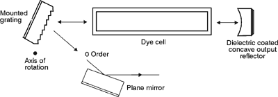
The resolution or chromatic resolving power of a grating describes its
ability to separate adjacent spectral lines. Resolution generally is
defined as (40) The limit of resolution of a grating is theoretically R = mN, where m is the grating order and N is the total number of grooves illuminated on the grating. To increase the resolution we could think of increasing N by obtaining a finer-ruled grating. However, you must know that, if you do this, certain orders disappear and the maximum value for m decreases. You get a more useful expression for resolution by substituting for m from the grating equation and arriving at Equation 2.
(41) Since (sin qi + sin qm) can have a maximum value of 2, the maximum resolving power at any wavelength turns out to be equal to 2 Na/l, where N is the number of slits and a is the slit spacing. So the product Na is the illuminated width w of the grating. At 500 nm a 15-cm grating will have a maximum resolution of:
Types and Uses of Gratings (42) Gratings can be either plane or concave. Plane gratings are usually less expensive and easier to control in the manufacturing process. Concave gratings, however, offer the added advantage of focusing. This eliminates one element such as a lens from the optical system. (43) Groove spacing is a wide open variable in gratings. For useful diffraction, the spacing must be at least 2/3 of the longest wavelength of interest. But in some cases it can be as much as 100 wavelengths or more. Rulings as fine as 3600 lines per millimeter can be made. This is a spacing of about half the wavelength of visible light. (44) One of the most widely used applications of the diffraction grating is in spectroscopy. The spectroscope is used to study the optical spectra of incandescent sources to determine their composition, temperature, or motionas in stars moving toward us or away from us. (45) Figure 13 shows a simple grating spectroscope that’s used for analyzing the spectrum of a light source assumed to emit a number of discrete wavelengths or "spectral lines." The light from source S is focused by lens L1 onto slit S1 placed in the focal plane of lens L2. The collimated light emerging from collimator C falls on the grating G. Rays of light associated with a particular interference maximum occurring at angle q form a parallel beam that enters the camera or field lens L3. The image of the slit thus is focused onto plane F–F ' and is examined with the magnifying eyepiece E.
Fig.
13 (46) A typical pattern that you might see with a spectroscope is shown in Figure 14. The lines actually appear as different colors, and their spacings and individual color tell much about the properties of the source.
Fig.
14 (47) Instruments much like that of Figure 13 are used to learn many facts about the age and composition of planets and stars. The light falling on a telescope lens from the stars may be sent through a grating. Then the spectrum formed by the starlight is studied to tell important facts about bodies billions of miles away. (48) Two special ways of using a grating as a spectrograph are important enough to deserve mention. The first is the autocollimating or "Littrow" scheme. As shown in Figure 15a, the slit source is at the focus of a collimating lens positioned close to the grating G. The grating is rotated on an axis parallel to the grooves to select the diffraction wavelength. The chosen light returns through the lens and is refocused near the original slit. This type of spectrograph is generally more compact than the others.
Fig.
15 (49)
Compare the geometry in Figure 15b of the
Littrow configuration for a blazed reflection grating to Figure 11.
Note that the incident and diffracted rays are nearly parallel to the
blaze normal NB such that (50) The spectrometer shown in Figure 16 uses two mirrors to control the light as the grating is rotated for a spectral scan.
Fig.
16 (51) Field stops and stray light baffles must be used to prevent reflection from one slit to another and to control scattered light within the system. These types of instruments are sometimes used as monochromators to select or filter out one single wavelength of light from many wavelengths present. (52) Another important use of the diffraction grating is in wavelength tuning and selectivity in laser cavities. There are two ways of using a grating as part of a laser cavity. A plane diffraction grating can be used as the "total" reflector (Figure 17) or as the "output" reflector (Figure 18) in a laser cavity, or as an intermediate reflector to "fold" the cavity (not shown).
Fig.
17
Fig.
18 (53) You can tune the output wavelength of the dye laser by turning the diffraction grating end reflector about an axis parallel to the grooves. Using a grating as one of the reflectors in a dye laser causes the spectral line width of the output to be reduced to a narrow region around the diffracted wavelength.
Care and Cleaning of Gratings (54) Good reflectivity is achieved in modern gratings by applying an evaporated aluminum or other metallic coating to the replica of the master grating. The aluminum coating is rather soft, as well as very thin, and is placed on a plastic replica. Both are easily damaged. (55) Foreign matter such as dust and fingerprints seriously alters the grating’s performance. Fingerprints and oral spray are ever-present hazards. Gratings should be given maximum protection from contamination, and the utmost care in necessary handling. Safe cleaning techniques are very limited and should be attempted by experts. (56) Table 1 is a composite summary of the properties of gratings that you must consider when you select a grating. Table 1. Properties of Diffraction Gratings
HeNe laser Transmission grating Reflection grating Screen Optical bench and mounts for gratings Mercury arc or helium arc lamp Measurement of Grating Spacing and Resolving Power
Determination of Wavelength of a Light Source
"Handbook of Diffraction Gratings—Ruled and Holographic." Metuchen, NJ: Prepared by the staff of JoBin-Yvon, Inc. Jenkins, F., and H. White. Fundamentals of Optics, 4th edition. New York: McGraw-Hill, 1976. Kingslake, Rudolph, ed., Applied Optics and Optical Engineering, Vol. V., New York: Academic Press, 1969. Pedrotti, Frank L., and Leno S. Pedrotti. Introduction to Optics, Chapter 20. Englewood Cliffs, NJ: Prentice-Hall, 1987.
|





 , where Dl is the
difference in wavelength between two equal intensity spectrum lines
that are just separated.


